
 |
Related Topics: | |
The Graphical Dependency Viewer, accessed by clicking the Diagram View button in the Dependency Viewer, offers a diagram-based alternative to help you understand the connections among resources in your project.
To understand how to use the Graphical Dependency Viewer, consider the example shown in the Dependency Viewer topic:
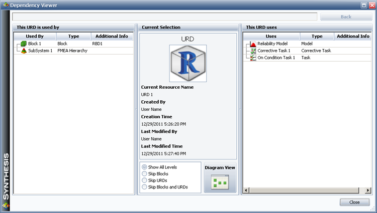
Clicking the Diagram View button in the window shown here will yield a diagram view that shows only the main item (in this case, the URD), which is marked with a flag:

To view a graphical representation of the information shown in the Dependency Viewer (i.e., one level of precedents and one level of dependents), choose Home > Precedents > Add One Level Precedents and Home > Dependents > Add One Level Dependents:
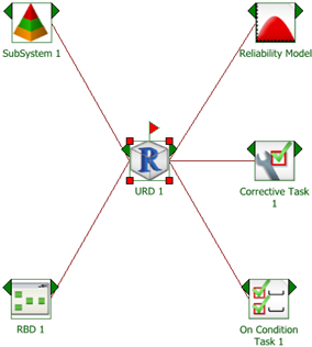
Further, assume that you want to see all levels of precedents and dependents for the URD. Choose Home > Precedents > Add All Precedents and Home > Dependents > Add All Dependents:

We can now see that Block 1 is used in RBD 1, and that Corrective Task 1 uses a model, a spare part pool and a crew.
You can select any item shown in the diagram and use the Add and Delete commands for precedents and dependents to expand or refine which dependencies are shown. To set a different item as the main item in the diagram, select the item and choose Home > Diagram > Set Block as Main.
Use the commands in the Options group of the Ribbon's Home tab to specify how the diagram will be constructed:
Select Reuse Items to show each item only once in the diagram. For example, if you are viewing a URD that is used by two blocks in the same diagram and you choose Home > Precedents > Add All Precedents, the Reuse Items command will affect the display as shown next:
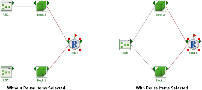
This command must be selected before the diagram is created, or you must clear the current diagram to apply it.
Use the Show Blocks and Show URDs commands to determine whether blocks and/or URDs are shown as intermediate steps between diagrams and models.
Select Show Item ID to display the internal ID assigned to each resource, block and/or diagram.
Additional commands allowing you to configure the diagram (including the Diagram Style window, the Block Style window and the Connector Style window are available on the Home tab of the Ribbon. The Diagram tab of the Ribbon offers zoom options and printing options, as well as the ability to copy the diagram or to export it as a graphics file.
© 1992-2013. ReliaSoft Corporation. ALL RIGHTS RESERVED.