
| Related Topics: | ||
The FMRA can perform a variety of analytical and simulation-based calculations. These calculations are based on the configuration of the FMRA hierarchy and the properties that you define for the records in the hierarchy.
This topic contains information on:
To perform any of the FMRA's calculations, you must first set up the FMRA hierarchy and define the relevant properties for each record. Typically, the initial setup is done in Xfmea/RCM++; it is possible, however, to perform basic functions in BlockSim:
Add the system and all the records that could impact its reliability to the FMRA hierarchy. See Working with Records in the FMRA.
Make sure that a reliability is defined for all records, either by defining at that level or by inheriting. Items will typically inherit their reliability from their sub-items and cause records. Thus, URDs will typically be assigned at the item level and cause level. In some cases, you may have to assign URDs at the failure or function level. For example, you would assign a URD at the failure level if you knew the probability of a particular failure mode occurring, but you didn't have that information for its causes.
Make any necessary changes to the diagrams to reflect the actual reliability-wise configuration.
Define the operating time at which calculations will be performed by selecting the system in the FMRA hierarchy or opening the system diagram and choosing FMRA > Inheritance > System Settings. In the System Settings window, enter a value in the Operating Time field.
For any calculated results, you can use the FMRA > Calculations > Highlight command to apply a color-coding gradient to the results shown in the column, from green (least "desirable" result) to red (most "desirable" result). This command toggles highlighting on and off.
If you are using analytical FMRA diagrams, to calculate the reliabilities and/or probabilities of failure for all of the records after you set up the FMRA hierarchy, choose FMRA > Calculations > Calculate Tree. The reliability or probability of failure for each record will appear in the relevant column of the FMRA, if the column is selected to be displayed.
You can also choose FMRA > Calculations > Calculate Branch to calculate results only for items within the selected system.
If you are using simulation FMRA diagrams, the FMRA can also be used to perform simulation-based calculations to predict the system's availability, the cost of operation and other values based on the reliability and the maintenance characteristics of the FMRA records.
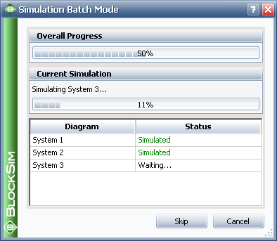
To perform system availability and cost calculations, set up the FMRA and then choose FMRA > Calculations > Simulate Tree Elements. The Simulation Batch Mode window will open. You can select to include any of the systems in the FMRA in the simulation. You can select the check box in the Available Diagrams header to select all diagrams. Each diagram that is selected for simulation in batch mode must have its own simulation settings defined, as explained in the Simulation Batch Mode topic. Once you have specified all necessary settings, click Run to perform the simulation. The Simulation Batch Mode window will change to show the status of the simulations, as shown next. While simulation is in progress, you can click Skip to stop simulating the current diagram and move on to the next one or Cancel to stop the simulations entirely.

Once the simulations have been completed, you can click Back to return to the original view of the Simulation Batch Mode window, where you can select different diagrams or change simulation settings, or Run to run the batch simulation process again with the same settings.
You will not be able to perform other operations in BlockSim while the simulations are being performed.
The following values are obtained from the simulation and may be shown on the FMRA tab of the System panel. To change which results columns are visible, right-click the column headers of the FMRA, then click Customize Columns.
Operating Cost displays the total costs that accrued during the simulation time.
Cost Per Operating Time displays the operating cost divided by the total operating time.
Note: It is not possible to simulate failure times for components whose reliability is defined by a constant value. Failure times can be simulated only in contexts where reliability is time-dependent. Thus, the calculated operating costs for any component with a constant reliability will be zero. In these situations, it may be advisable to change the model from a constant value to a time-dependent distribution.
Reliability (Simulation) displays the reliability (obtained via simulation) at the end time specified in the simulation settings.
Availability displays the average availability (i.e., uptime divided by operating time). This is a metric that reflects the probability that the system is operational (not failed or undergoing repair) when it is requested for use during the simulation.
RS FCI shows the ReliaSoft Failure Criticality Index for each item. This is a relative index showing the percentage of times a failure of the component caused a system failure (i.e., the number of system failures caused by the component divided by the total number of system failures). Note that this relates only to failures; it does not include every event that could bring the system down (such as routine maintenance).
RS DECI shows the ReliaSoft Downing Event Criticality Index for each item. This is a relative index showing the percentage of times that a downing event of the component caused the system to go down (i.e., the number of system downing events caused by the component divided by the total number of system downing events). Note that this only relates to downing events with a non-zero duration.
RS DTCI shows the ReliaSoft Downtime Criticality Index for each item. This is a relative index showing the contribution of each component's downtime to the system’s downtime (i.e., the system downtime caused by the component divided by the total system downtime).
© 1992-2013. ReliaSoft Corporation. ALL RIGHTS RESERVED.