![]()
![]()
| Related Topics: | ||

Node blocks are like switches that diagram paths move through. A node allows you to model an alternative form of redundancy known as k-out-of-n redundancy. A k-out-of-n node block can have n paths leading into it and requires that k out of n paths must function for the system to function. There must be at least one path leading into a node; therefore, a node block cannot be placed as the starting block for a diagram.
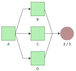
The configuration in the figure shown next displays a k-out-of-n node block where either Block B, Block C or Block D can fail without causing system failure, but if two of the blocks fail, the system will fail.
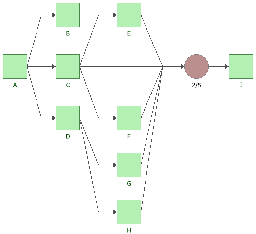
The figure shown next displays another k-out-of-n node block, this time used in a complex configuration. If more than three of the five blocks leading to the node block fail, the system will fail.
You can add node blocks to the diagram by choosing Diagrams > Diagram Tools > Add Node.
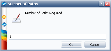
Double-clicking the node block or selecting Diagrams > Format & Style > Edit Block > Block Properties opens the properties window for the node block, which allows you to specify the number of paths that must reach the node block in order for the system to succeed.
© 1992-2013. ReliaSoft Corporation. ALL RIGHTS RESERVED.